Check out these impeller manufacturing photos:
Image from page 545 of “The manufacture of pulp and paper : a textbook of modern day pulp and paper mill practice” (1921)

Image by Web Archive Book Images
Identifier: manufactureofpul03join
Title: The manufacture of pulp and paper : a textbook of modern pulp and paper mill practice
Year: 1921 (1920s)
Authors: Joint Textbook Committee of the Paper Market Stephenson, J. Newell
Subjects: Papermaking Wood-pulp
Publisher: New York : McGraw-Hill Book Business
Contributing Library: NCSU Libraries
Digitizing Sponsor: NCSU Libraries
View Book Page: Book Viewer
About This Book: Catalog Entry
View All Images: All Images From Book
Click right here to view book on the internet to see this illustration in context in a browseable online version of this book.
Text Appearing Prior to Image:
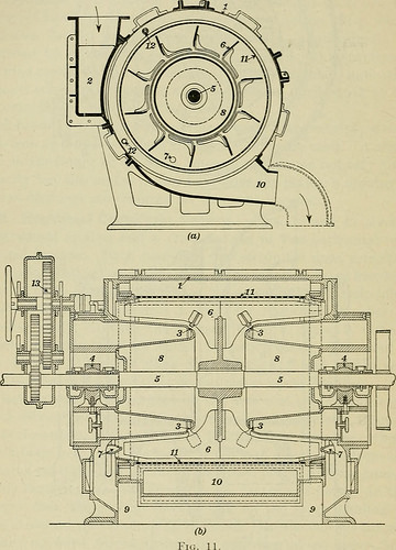
34 Treatment OF PULP 17 have been, than if it flowed in a single stream to the impeller blades.This matter of distribution is essential, considering that it has a directbearing on the capacity, horsepower consumed, and the efficiencyof the screen. In Fig. 11. the stock enters from each sides of
Text Appearing Following Image:
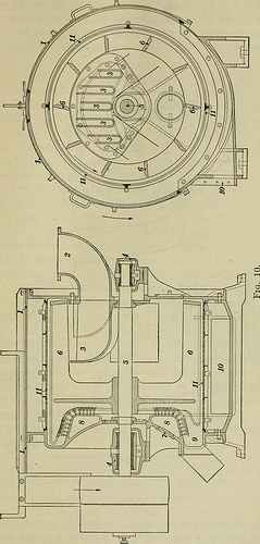
the center via the orifices three. Impellers, as well as distrib-utors and manner of introducing stock, differ in design and style, and theseare the chief variations in this kind of screen, as produced by variousmanufacturers. The impeller, or agitator, consists of a shaft §7 FINE SCREENING 35 with blades set at normal intervals about it it is generally madeof cast iron for use with all classes of stock except sulphite,when bronze is advisable, to resist the acid. The impeller shouldrotate at a speed that has been predetermined to suit the condi-tions and the class of stock to be screened. The screen plates 11are generally rolled copper sheets, perforated with holes varyingfrom .05 in. to .07 in. or bigger in diameter a frequent size forgroundwood, sulphite, and soda pulps is -aV in. (.0625 in.). Forthe screens right here shown, the screen plates are secured to theframes, which are bolted to the screen body. In some styles,provision is created for the rotation of the screen plates at a slowspeed, to facili
Note About Photos
Please note that these pictures are extracted from scanned web page photos that may have been digitally enhanced for readability – coloration and look of these illustrations may not perfectly resemble the original perform.
Image from page 544 of “The manufacture of pulp and paper : a textbook of modern pulp and paper mill practice” (1921)

Image by World wide web Archive Book Images
Identifier: manufactureofpul03join
Title: The manufacture of pulp and paper : a textbook of modern pulp and paper mill practice
Year: 1921 (1920s)
Authors: Joint Textbook Committee of the Paper Business Stephenson, J. Newell
Subjects: Papermaking Wood-pulp
Publisher: New York : McGraw-Hill Book Organization
Contributing Library: NCSU Libraries
Digitizing Sponsor: NCSU Libraries
View Book Page: Book Viewer
About This Book: Catalog Entry
View All Images: All Pictures From Book
Click here to view book on the web to see this illustration in context in a browseable on-line version of this book.
Text Appearing Just before Image:
is the plate cleaning shower, and 13 is a caseenclosing gearing for rotating screen plates while cleaning. These screens are operated by the action of centrifugal force,which drives the stock against the encircling screen plates, throughthe perforations, to the outside. The principle is basic: when-ever a body is brought on to revolve, it tends to move away from thecenter of rotation, and the more rapidly the speed of rotation the greateris this tendency, i.e., the higher is the centrifugal force. In thepresent case, there is no force acting on the stock tending toforce it toward the center, with the outcome that the stock is thrownradially outward, forced against the enclosing screen plates, andthrough the perforations. The stock enters by means of the inlet two, Fig. 10 or 11, and is sepa-rated into a number of streams by the stationary distributors (com-partments) 3, from which it flows to the impeller blades six thisinsures a much much better distribution of the stock, breaks it up as it FINE SCREENING 33
Text Appearing Following Image:
34 Therapy OF PULP 17 have been, than if it flowed in a single stream to the impeller blades.This matter of distribution is critical, since it has a directbearing on the capacity, horsepower consumed, and the efficiencyof the screen. In Fig. 11. the stock enters from each sides of
Note About Pictures
Please note that these pictures are extracted from scanned page pictures that may have been digitally enhanced for readability – coloration and look of these illustrations may not perfectly resemble the original operate.