Check out these machining turbine rotors pictures:
Image from page 529 of “The steam engine and turbine a text-book for engineering colleges” (1911)

Image by Net Archive Book Pictures
Identifier: steamengineturbi01heck
Title: The steam engine and turbine a text-book for engineering colleges
Year: 1911 (1910s)
Authors: Heck, Robert Culbertson Hays, 1870-
Subjects: Steam-engines Steam-turbines
Publisher: New York, D. Van Nostrand business
Contributing Library: The Library of Congress
Digitizing Sponsor: The Library of Congress
View Book Web page: Book Viewer
About This Book: Catalog Entry
View All Images: All Photos From Book
Click right here to view book on the internet to see this illustration in context in a browseable on the web version of this book.
Text Appearing Ahead of Image:
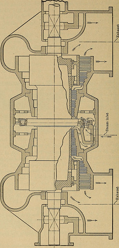
, at D then the remainder of the right-hand end of the rotor isbalanced by carrying the condenser stress more than to the outer face ofP2. This plan calls for a lot significantly less enlargement of the casing for thebalance discs and inside of a single stuffing box (at the proper) the steampressure is not far from atmospheric, so that liability to air leakage ismuch diminished. In Fig. 356, regular admission is at A, and underheavy overload steam is bypassed to B. The introduction of one or two initial, higher-pressure stages of theCurtis variety not only replaces the little-region reaction stages in whichleakage is of critical magnitude, but also makes straightforward an arrangementwhich is more or less self-balanced — see Fig. 26. The double-flowsystem, represented by Fig. 357, nonetheless additional facilitates the eliminationof end thrust. A excellent description of different types of the Westinghouse double-flowturbine will be discovered in Power for June 16, 1908 all of them have flow 514 Design AND Construction OF THE TURBINE. [Chap. X.
Text Appearing Soon after Image:
MO JO ^ 02 P bO § 50 id)] Different Types OF THE TURBINE. 515 from the middle toward the ends, hence requiring two stuffing boxestight against leakage of air into the condenser, just as in Fig. 25.For low-stress service, the impulse stages are naturally omittedthen flow from the ends toward the middle, as in the Brush-Parsonsturbine, No. 49 in Table 20, reduces the danger of air leakage to aminimum. (e) Low-pressure and Mixed-flow Turbines. — The low-pres-sure turbine differs in no essential distinct from the decrease stages of thesame kind of full-range machine. If the supply of engine exhaust isirregular or intermittent, provision need to be created for feeding the tur-bine directly from the boiler. The simplest method is to pass live steamthrough a decreasing valve, cutting it down to the standard admissionpressure of the turbine. A reaction turbine should be operated in thisway, unless a unique group of higher-pressure stages, typically runningidle, is provided. But an impulse turbine may, mo
Note About Pictures
Please note that these pictures are extracted from scanned page images that may have been digitally enhanced for readability – coloration and appearance of these illustrations may not completely resemble the original perform.
Image from web page 372 of “Twentieth century hand-book for steam engineers and electricians, with questions and answers ..” (1905)

Image by Net Archive Book Pictures
Identifier: twentiethcentury03swin
Title: Twentieth century hand-book for steam engineers and electricians, with queries and answers ..
Year: 1905 (1900s)
Authors: Swingle, C. F. [from old catalog] Horstmann, Henry Charles, 1858- [from old catalog] Tousley, Victor Hugo, 1875- [from old catalog]
Subjects: Steam engineering Electrical engineering Steam turbines
Publisher: Chicago, F. J. Drake & co.
Contributing Library: The Library of Congress
Digitizing Sponsor: The Library of Congress
View Book Page: Book Viewer
About This Book: Catalog Entry
View All Photos: All Images From Book
Click here to view book online to see this illustration in context in a browseable online version of this book.
Text Appearing Ahead of Image:
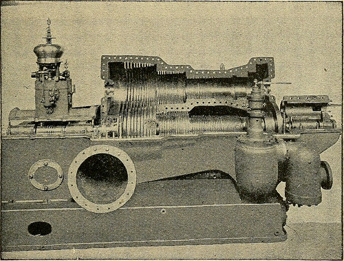
ed would be 38,one hundred R. P. M. But such a speed isbeyond the limits of strength of material. As before stated, the Westinghouse-Parsons turbineoperates on both impulse and reaction principles, andby a technique of compounding, which will be explainedlater on, the peripheral velocity of the machine hasbeen so reduced as to bring it within practical limitswhile at the exact same time the energy worth of the steam isutilized to a high degree of efficiency. The speed of the Westinghouse-Parsons turbine THE WESTINGHOUSE-PARSONS STEAM-TURBINE 361 varies from about 750 R. P. M. for a five,000 K. W.machine to three,600 R. P. M. for a 400 K. W. turbine. Fig. 129 is a basic view of a 400 K. W. turbinegenerator unit. Fig. 130 shows a 600 H. P. machinewith the upper half of the cylinder, or stator as it istermed, thrown back for inspection. Fig. 131 is asectional view of a Westinghouse-Parsons turbine, andit will be noticed that there are 3 sections or drums,steadily increasing in diameter from the inlet A to
Text Appearing Following Image:
figure 130. the third and final group of blades. This arrange-ment could be likened in some measure to the triplecompound reciprocating engine. By reference to Fig. 130 it will be seen thatt theinside of the cylinder is studded with rows of smallstationary blades and that the rotor or revolving partof the machine is also fitted with rows of modest blades,equivalent in shape and dimensions to the stationary 362 ENGINEERING blades. When the upper half of the cylinder is inposition, every row of stationary blades fits in betweentwo corresponding rows of moving blades. Thisarrangement may possibly perhaps be far better understood byreference to Fig. 132, which illustrates the relation ofthe stationary blades to the moving blades when inposition, and also shows by the arrows the course ofthe steam and its change of direction brought on by thestationary blades. For the purpose of explanation the moving blades or
Note About Photos
Please note that these images are extracted from scanned page photos that may possibly have been digitally enhanced for readability – coloration and appearance of these illustrations could not completely resemble the original operate.
